mastodontech.de ist einer von vielen unabhängigen Mastodon-Servern, mit dem du dich im Fediverse beteiligen kannst.
Offen für alle (über 16) und bereitgestellt von Markus'Blog

Serverstatistik:

1,4 Tsd.
aktive Profile

#diy_electronics

0 Beiträge0 Beteiligte0 Beiträge heute
Fortgeführter Thread

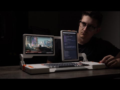
This project was held up 4evah (in other words, about two weeks) because the screws was so damn hard to get. Getting PCBs made? No prob, they were shipped fast from the fab within a day or two. Finding electronic components? They were picked and delivered from Kentucky to my door in Norway within 48 hours. Printing the case took an hour or so in my basement. But screws? Not so easy. Shenzhen came to the rescue again, they came on a slow boat from China. #diy_electronics

Fellow queer techies, I need some help: I am currently doing a way-too-big electronics engineering project, and like I'm good mostly but I'm really struggling to figure out the power management part of it, as the ref. implementations of chips like the TI series of battery chargers are... opaque to say the least. If anyone would like to help me figure it out it would be most appreciated :Blobhaj_Plead_2:

I'm working on a connector design to use a piece of FR4 copper clad as the power connector on an HP power supply (it has a card edge exposed). This should give a large contact surface area vs the bolts I see people drilling through these. Plus, it's removable. The slots are for soldering power wires to the copper clad in place. The wires will come out the top. If this works, I'll add a fuse block on the side that takes automotive blade-type fuses. #diy_electronics #electronics

Ich habe soeben eine Leiterplatte beim Verlöten mit dem 4S Batteriepack (LiPo4) aufleuchten lassen. Offenbar hatte ich eine 22w statt einer 100w Platine bestellt 🫣 die deutlich überfordert war und das eindrucksvoll zur Schau stellte.

Eine neue ist bestellt, aber aus China wird das eine Weile brauchen. Mal schauen welche Bausteine sich noch verwenden lassen. Kann die Kurze mal mit dem Papa entlöten üben.

Fortgeführter Thread

That is just too many wires in too little space. This would have been quite a bit easier with multiple breadboards side by side. It still needs about a dozen more wires, but no more in the middle of all that.

And yes - one of those shift registers is "backwards" compared to the others. It was too much of a hassle to wire with 16 outputs all on the same side.

Sharing a little prep-work on a project I'm starting on. I just wanted to make sure these eBay special displays worked. They do work, and they're awfully bright, even at 11mA per segment (they're rated to 20, per the seller).

I will definitely share more later, once I get them moved to a protoboard. The breadboard is just *too annoying* with this many pins, and the display oriented in the wrong direction.

"If you wanted to create a floppy disk from scratch, you'd first have to create the universe." Well, Carl Sagan said that about apple pie, but it basically holds true no matter what you want to create from scratch. Turns out trying to create new floppy disks is also not a small endeavor. This is the second person seriously trying afaik so far, and he's coming pretty close already. I especially like the chapter called "chasing microns". This is really something special, so go watch it 📺💾
#diskette #disketten #floppydisk #floppydisks #vintagecomputing #diy_electronics
youtu.be/TBiFGhnXsh8

Guys.. please... stop using your soldering irons at >350º celsius... You are just obliterating your tips...

It is the fifth time that I see a video of dudes roasting their tips at 480º celsius...

If 350º (max) is not enough for you, change to an another tip shape or help your soldering iron with the hot air gun or a preheater platform.